An Apple Fell from a Tree
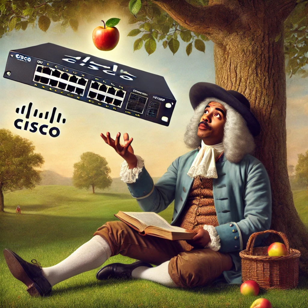
It hit me on the head with force of a couple Newtons. Eureka, the gravity of the simplistic, yet genius, approach to problem solving. Archetypes. System engineering. C++ courses taken in days of yore. CCNA studies of not that many years pasts. I made the connection in my neural pathways, a bridge to the root ideology that the wonderful Radia Perlman used to come up with the notorious STP, Spanning Tree Protocol.
It was two years ago, Nov 10th, 2020, when I first posted my crude thought, “When you realize you can diagram a stp topology like a tree data structure in programming… Why haven’t I heard anyone make that connection before? 🤯” That is verbatim what I said, which prompted some good questions from some network professionals that I shared this epiphany with. I explained more, including making this ugly raw doodle with a stylus on a Samsung Galaxy I had at the time:
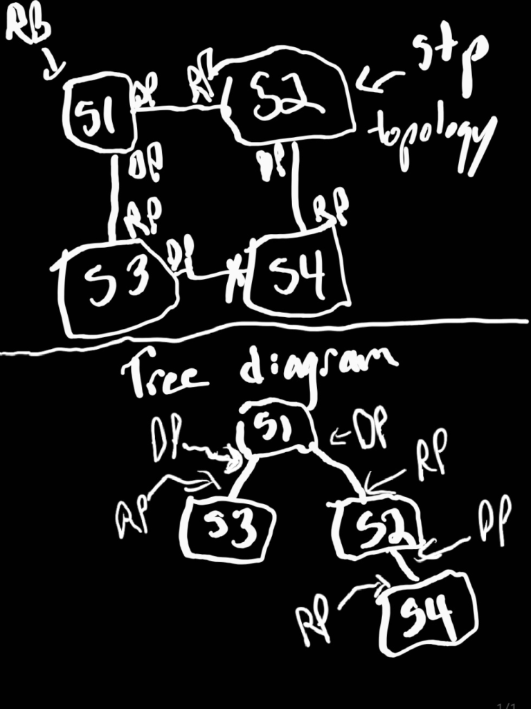
I recently was thinking about this again. In the course of revisiting, I thought maybe a less crude, more technical, and thorough deep dive might help. Spanning tree protocol is often a topic is see as a point of confusion on the internet when I look at forums and social media, especially for those studying for certification exams like the CCNA or CCNP. I decided I wanted to make a better diagram, give a thorough explanation, and create a python script that can visualize a layer-2 topology in a tree structure like the diagram in an automated fashion. I plan to discuss the raw, 802.1d, protocol design. Adaptations and revisions of STP may be a conversation or post for future times.
Tree Structure (ADT – Abstract Data Type)
A tree data structure consists of nodes. Each node holds a value. Each node has a list (or array) which point to, or reference, their child nodes. Trees are hierarchical is nature. A tree structure has a root node at the top. Every node, except the root, has exactly one parent (no more or less). Due to their hierarchical concept trees are used in many fields, especially in technology. So to now surprise, tree structures are used in programming and network engineering. So let’s discuss the terminology better, as STP is the marriage of three concepts: tree, programming, and networking.
Key Terms:
Root: The topmost node in a tree; it has no parent. In blockchain, this is the Genesis block. In biblical genealogy, this is Adam.
Node: An element in the tree. This element contains data. It could be the root or not. It could be a parent or not.
Parent: A node that connects to one or more child nodes.
Leaf: A node with no children.
Child: A node directly connected below another node. In this case the element above is its parent.
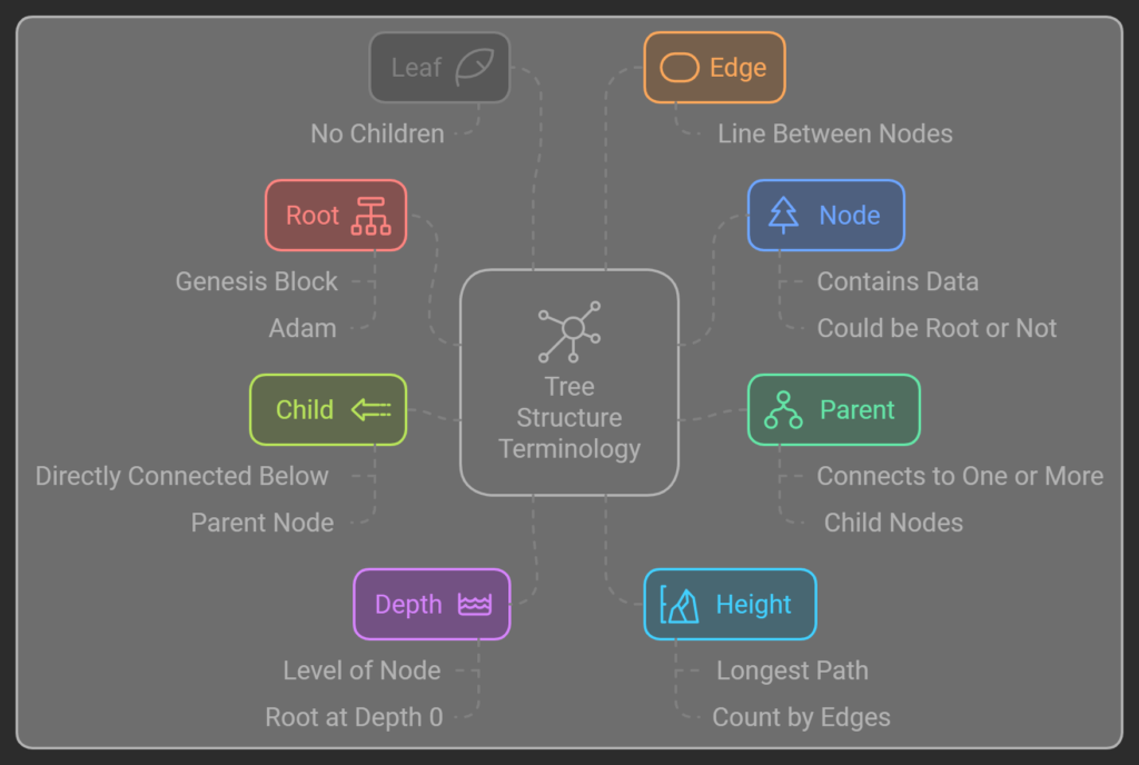
Edge: A connection between two nodes. A a tree diagram this is the line between a parent to a child.
Depth: The level of a node in the tree, where the root is at depth 0. If my parent is the root, my depth is 1. In such a case, my children have a depth of 2, a child of my children is a depth of 3, so forth, and so on.
Height: The length of the longest path from the root to a leaf. Of all the nodes in a tree, which has the largest depth? Let’s say, there are two equally valid ways to count this. For the sake of brevity, we don’t need to deep dive, you can count by edges (height = depth) or nodes (height = depth+1). The short explanation, do you consider a tree with just a root node to be 0 or 1 in height? Valid reasons for both trains of thought exist. I advise to follow best practices and consistency for the job or environment in respects. I count by the edges.
Consider:

In this tree:
A is the root.
B and C are children of A.
B and C are parents of D, E, F, and G.
D, E, F, and G are leaves as they have no children.
The depth of C is 1.
The height of the tree is 2.
Switching Loops: BUM traffic and storms
First, let’s discuss the problem. Why is there a (STP) Tree Protocol? What issue does it solve? What was there to gain?
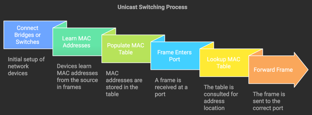
Pre-STP, connecting bridges or switches in a loop was a faux pas. These devices learn MAC addresses from the Ethernet frame. This is used to populate the MAC address table. When a frame enters a port, the network appliance looks up the MAC address table. The switch finds the port where the destination MAC address is and forwards it out that port. That is how unicast switching works.
But there are situations where this is not the case.
BUM BUM BUM BUM
On queue, there are three circumstances where layer 2 traffic isn’t switched to the destination port. BUM stands for Broadcast, Unknown Unicast, and Multicast. Broadcast and Multicast packets are special types of packets, mostly famously seen in the wild in routing protocols, ARP, DHCP, and other forms of network communication. Unknown unicast occurs when a destination MAC address is not in the MAC address table.
Flooding and storming
When a BUM frame enters it is flooded out (egress) every port, except the port it entered (ingress).

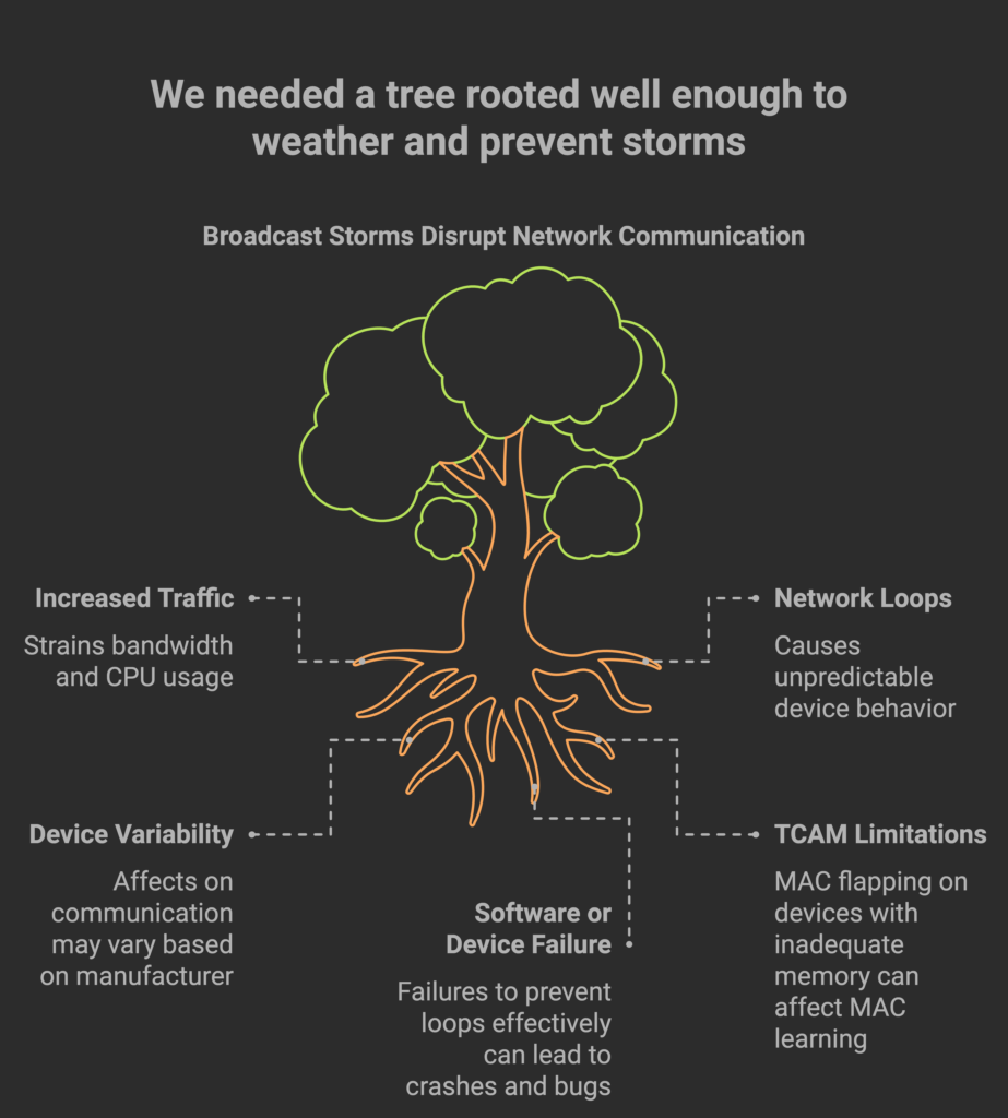
If a switch is connected to other switches in a loop and there is ingress BUM traffic, the traffic can loop around in the topology indefinitely. Not only that, but the traffic is flooded, in a log sprawl of devices with many loops between the traffic can increase with each passing loop. This typically called a broadcast storm, however, it may occur with unknown unicast or multicast traffic as well. Therefore, I typically only say storm, unless I can specifically say a specific form of BUM traffic is the cause.
Storms can wreck devastating effects in the network topology. As the traffic increases, so does the strain of bandwidth and CPU usage. Due to broadcast storms, I have encountered all forms of wonky symptoms. I’ve witnessed it causing switches to crash and reboot seemingly at random. I’ve witnessed where broadcast storms caused only half the connected devices to be unable to communicate. The side effects can vary based on device manufacturers, models, TCAM, number of end devices, number of switches in the loops, number of links in the loop, and so forth and so on. Now enters Radia Perlman, an engineer, who contributed one of my top 10 favorite networking protocols, STP, to eliminate loops in a switching architecture.
Radia Perlman

Radia Perlman is a software engineer, computer scientist, network engineer, and more. Known as the “Mother of the Internet”, she has accomplished and innovated a litany of things aiding in propelling digital communications. Aside from STP, she worked on IS-IS a well-known and widely used routing protocol that I have studied a bit and find fascinating. This MIT graduate ending up at a company called DEC (Digital Equipment Corporation) where she penned the ultimate tech poem, Algorhyme.
I think that I shall never see A graph more lovely than a tree.
A tree whose crucial property Is loop-free connectivity.
A tree which must be sure to span So packets can reach every LAN.
First the root must be selected. By ID it is elected.
Least cost paths from root are traced. In the tree these paths are placed.
A mesh is made by folks like me Then bridges find a spanning tree.
— Radia Perlman, Algorhyme
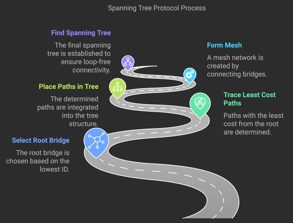
This poem outlines the algorithm she devised. It was the year 1985. Switches were not yet the staple device of layer 2 data transmission. It was the bridge that was widely used at this point, therefore most of the STP terminology refer to bridge. For example, “root bridge”, technically in today’s world is a root switch. As of now, 2024, it is perfectly fine to picture a switch instead of a bridge. Please note that the documentation, the experts, the veterans in the field, the cert exams, and Internet will use the proper terms as notated in the protocol.
Networking Spanning Tree Protocol
There are six important aspects when I think about STP: Bridge IDs, BPDUs, elections, port states, port roles, and timers.
Bridge IDs
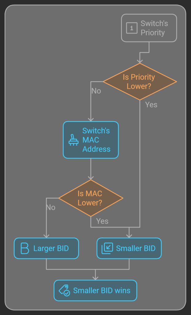
Every device in a STP topology has a Bridge ID, BID, that is a 8 byte number. Each switch has a MAC address (a 6 byte value) often called: a burned in address, BIA, or base MAC address from the factory (there are often ways to modify this though 😉). Every switch has priority (a 2 byte number), default typically is 32768 which is halfway between the minimum of 0 and maximum of 65535. The BID is the concatenation of priority then MAC. Therefore, a switch with a lower priority is always a smaller number. When two switches have the same priority, the one with a lower MAC has a smaller number.
BPDUs
Switches using STP by default send BPDU, multicast, frames every 2 secs from each enabled interface.
BPDU frames carry the info to run STP. There are two types: Configuration and TCN (Topology Change Notice).

Configuration BPDUs
Purpose: Configuration BPDUs are essential for establishing and maintaining a stable spanning tree topology. They are used for electing the root bridge, assigning roles to switch ports, and ensuring that only loop-free paths are active.
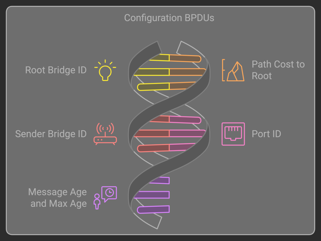
Key Fields in Configuration BPDUs:
Root Bridge ID: Identifies the root bridge, a central switch that all others reference.
Path Cost to Root: Indicates the cost from a given switch to the root bridge.
Sender Bridge ID: Identifies the switch sending the BPDU.
Port ID: The port number on the switch sending the BPDU.
Message Age and Max Age: Manage BPDU longevity and update intervals, limiting the age of the information within the BPDU.
When Configuration BPDUs Are Sent:
Network Initialization: When a switch first powers on, it sends Configuration BPDUs to broadcast its existence and participate in the election of a root bridge.
Topology Changes: If a network change occurs, such as a switch coming online, reconfiguration is necessary, so Configuration BPDUs are sent to re-evaluate the best paths.
Periodic Updates: Even in stable networks, Configuration BPDUs are periodically sent (typically every 2 seconds by default) to maintain the spanning tree structure and ensure stability.
TCN (Topology Change Notice) BPDUs
Purpose: TCN BPDUs notify the network of topology changes, such as a switch or device joining, leaving, or moving to another part of the network. These notifications trigger a recalculation of the spanning tree, ensuring switches quickly adapt to the change and update their MAC address tables.
Key Fields in TCN BPDUs:
TCN BPDUs are simpler than Configuration BPDUs and lack many of the complex fields, containing just enough information to signal a topology change.
When TCN BPDUs Are Sent:
Port State Changes: When a switch detects a port moving from a blocking or disabled state to forwarding, or vice versa, a TCN BPDU is triggered. This change indicates that a potential new path or device is available or that a current path is lost.
Device Connectivity Changes: If a device is unplugged or connects to a different switch port, the network topology alters. The affected switch sends a TCN BPDU to inform the root bridge of the change.
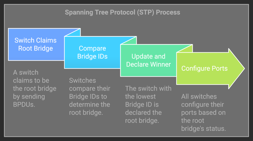
Election of a Root Bridge
- Every one claims to be king When a switch is powered up it begins send BPDUs. These BPDUs state that is the root bridge.
- Compare the BID of other contenders
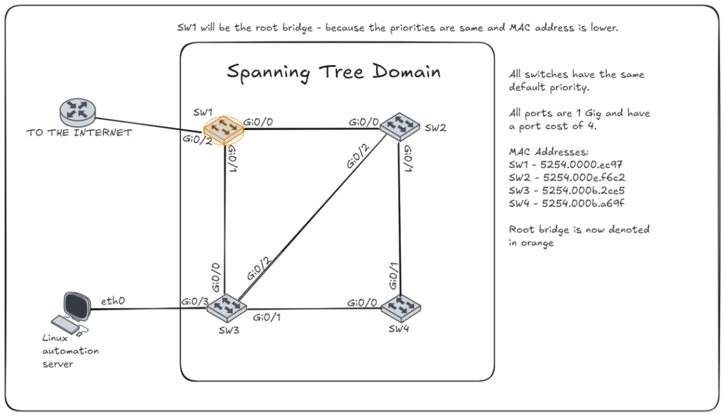
When other BPDUs are received, the BID the switch believes to be the root bridge is compared with the BID of the root bridge stated in the BPDU. The lowest BID wins. Priority first, and MAC address in case of ties in priority.
- Losers declares the winner king
When a superior BPDU is found, a switch then updates and begins to mark the BID in it’s BPDUs.
- The king becomes the point of reference
Every switch then configures there ports with the root bridge as a reference. The root bridge sets all its ports to forward. All other switches will set ports to block or forward based on information received in BPDUs. Each port will report their path cost to the root bridge based on BPDUs received plus the cost associated with their link speed (higher bandwidth links have lower costs), this calculation can vary based on version or adaptation of STP in use.
Port States
- Blocking: Listens for BPDUs but does not forward traffic, this prevents loops.
- Listening: Processes BPDUs and prepares to transition. There is data forwarding yet.
- Learning: Learns MAC addresses but still does not forward traffic.
- Forwarding: Fully active, forwards traffic and learns MAC addresses.
- Disabled: Administratively or physically down. Port is not participating in STP.
Port Roles
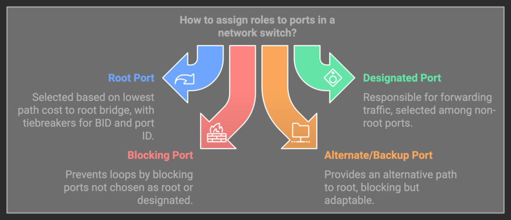
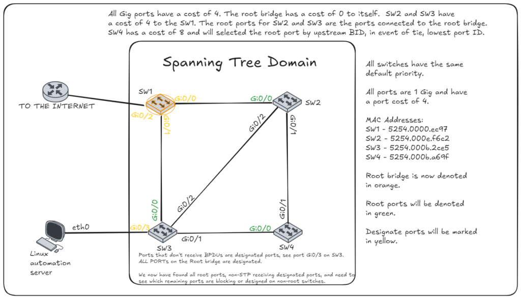
- Root Port: The port with the best path to the root bridge. Note: The root bridge will never have a root port and all other switches will have EXACTLY one root port. This port is selected by finding a few things:
- The interface receiving BPDUs containing the lowest path cost to the root bridge.
- In the event of a tie with path cost, the sending BID is the tiebreaker.
- The event the BID is the same, ergo the switch receives BPDUs of equal cost from the same switch on different interfaces, the upstream port ID is the tiebreaker. With STP decisions, the lower number is preferred.
- Designated Port: The port on a responsible for forwarding traffic to/from devices directly connected to the switch or further from the root bridge. Note: All ports on a root bridge or designated. Non-root bridge switches will have at least one port that is not a designated port, the root port.
- Blocking Port: A port placed in blocking state to prevent loops. Only non-root bridge devices will have a port in a blocking state. After the root port is selected, the remaining ports will be designated or blocked. If a port receives a superior BPDU and is not the chosen root it will become blocked. This must meet the same series requires: lower path cost, lower BID if equal, and then port ID as a final tiebreaker.
- Alternate/Backup Port (RSTP): Alternate path to the root bridge or a backup for the designated port. These ports are in a blocking state, but can change with topology.
Timers
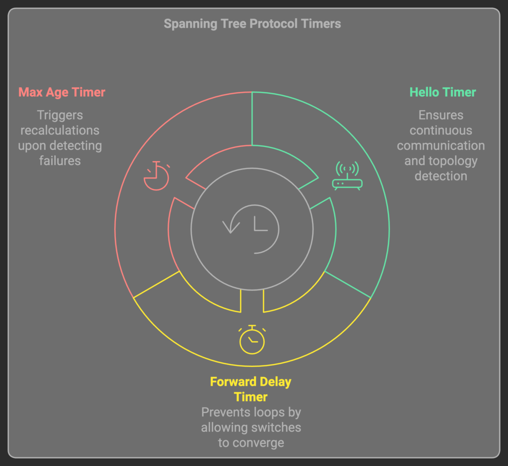
- Hello Timer:
Purpose: The interval at which the root bridge sends BPDUs to other switches.
Default Value: 2 seconds.
Significance: Ensures continuous communication in the network, allowing switches to detect topology changes.
- Forward Delay Timer:
Purpose: How long a port remains in the Listening and Learning states before transitioning to Forwarding.
Default Value: 15 seconds (for each state, totaling 30 seconds).
Significance: Prevents loops by giving enough time for switches to converge before forwarding traffic.
- Max Age Timer:
Purpose: The maximum time a switch will retain a BPDU before discarding it if no new BPDUs are received.
Default Value: 20 seconds.
Significance: Helps switches detect failures or topology changes and triggers recalculations.
Drawing the Tree
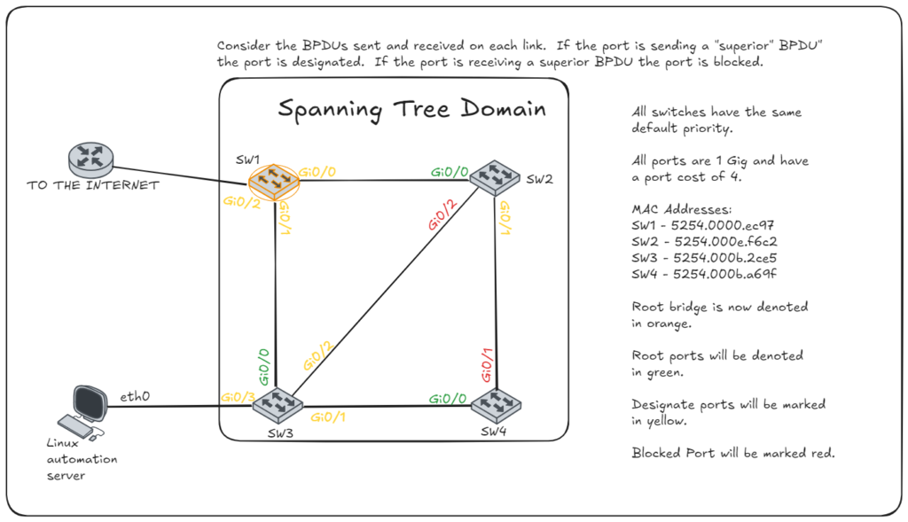
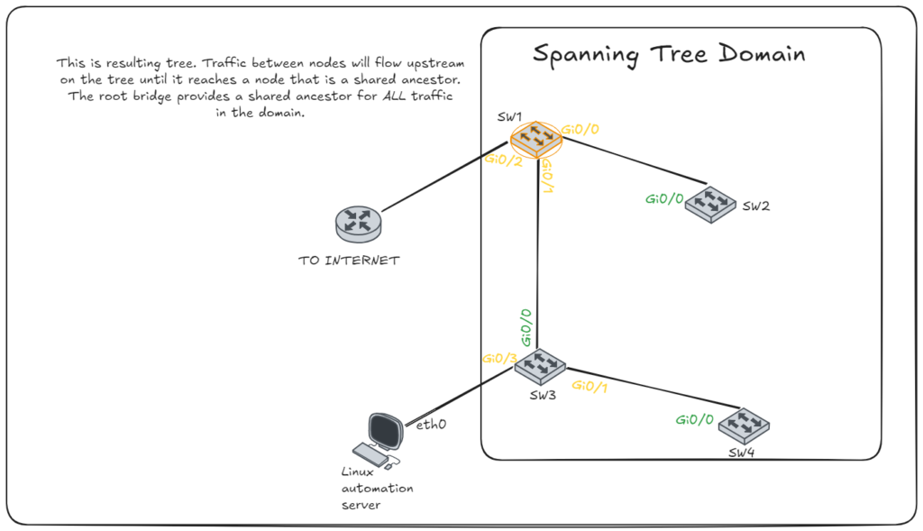
It important to grasp how a tree is structured and how STP works. The root is the ancestor of all nodes in the topology. Traffic will flow upstream through the parents (via root ports) until it reaches a shared ancestor of the destination. After which, it will flow downstream to the proper node (via designated ports).
This provides a logically hierarchy. If you can view the STP info on all nodes, or at least now the topology, MAC addresses, and priority, you can draw a tree in which you can visually trace the flow of the traffic. With a visual layout of the tree, it can become clearer for troubleshooting or modifying for optimality.
Notes for building and analyzing the tree
- Note this diagram isn’t factoring end devices such as: peripherals, PC, APs, servers, etc.
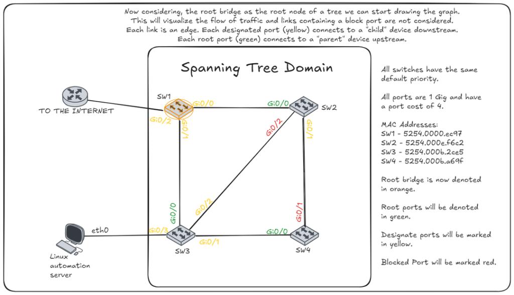
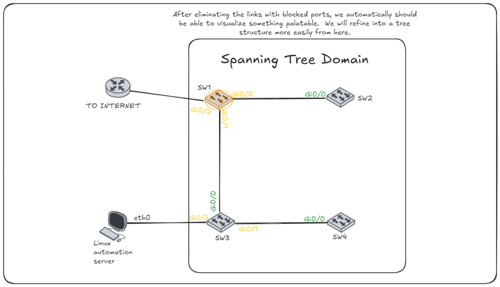
- Consider only the links forwarding traffic both ways, neither side is blocking. These are the edges.
- The root bridge is the root node.
- Each edge will correspond to a link with a designated port on one end with a root port on the other end.
- If a device was a root port, that is its connection to a parent node.
- If a device has a designated port that is forwarding bidirectionally, we know 2 things: the other side is a root port and therefore the other side is a child node.
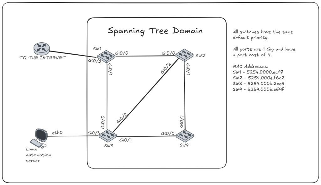
So now, we circle back to the original diagram I drew years ago. But this time I’ll recreate it manually to be more palatable, using a free online tool called Excalidraw. I’ll walk through the steps also.

Topology Changes
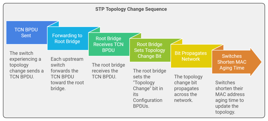
TCN BPDUs are initially sent from the switch experiencing the topology change.
Forwarding to the Root Bridge: Each upstream switch forwards the TCN BPDU toward the root bridge, notifying all switches along the path of the change.
Root Bridge Response: Once the root bridge receives the TCN BPDU, it responds by setting the “Topology Change” bit in its Configuration BPDUs. This flag propagates across the network, prompting all switches to shorten their MAC address aging time. This ensures that outdated entries are removed more quickly, helping switches learn the updated network topology.
There may be times where switches disconnecting or reconnecting can change the tree entirely. STP messages can be spoofed as well. So, being able to visualize the traffic flows can help, but also please review and consider implementing measures to reduce risks and increase stability.
Labbing it up
So I then labbed the concept. The idea was to write a script that was capable of accessing network switches and outputting a diagram of the spanning tree topology in the form of a proper tree diagram.
The steps taken:
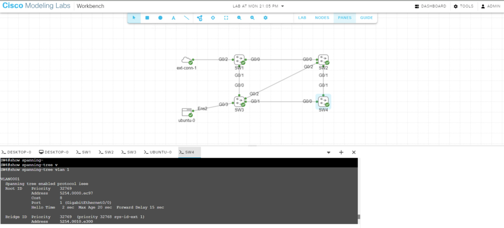
- Created the topology in Cisco CML (NOW THERE IS A FREE VERSION OF CML!!!)
- This is the topology I used when I manually draw the diagrams above.
- Using PyATS (specifically Genie) modules to parse each switch for the outputs of:
  show cdp neighbor
  show spanning-tree
The output of each command on SW4 looks like the following:
SW4#show spanning-tree vlan 1

VLAN0001
  Spanning tree enabled protocol ieee
  Root ID    Priority    32769
             Address     5254.0000.ec97
             Cost        8
             Port        1 (GigabitEthernet0/0)
             Hello Time   2 sec  Max Age 20 sec  Forward Delay 15 sec

  Bridge ID  Priority    32769  (priority 32768 sys-id-ext 1)
             Address     5254.0010.e300
             Hello Time   2 sec  Max Age 20 sec  Forward Delay 15 sec
             Aging Time  300 sec

Interface           Role Sts Cost      Prio.Nbr Type
------------------- ---- --- --------- -------- --------------------------------
Gi0/0               Root FWD 4         128.1    P2p
Gi0/1               Altn BLK 4         128.2    P2p
Gi0/2               Desg FWD 4         128.3    P2p
Gi0/3               Desg FWD 4         128.4    P2p

SW4#show cdp
SW4#show cdp ne
SW4#show cdp neighbors
Capability Codes: R - Router, T - Trans Bridge, B - Source Route Bridge
                  S - Switch, H - Host, I - IGMP, r - Repeater, P - Phone,
                  D - Remote, C - CVTA, M - Two-port Mac Relay

Device ID        Local Intrfce     Holdtme    Capability  Platform  Port ID
SW3.qwertysage.com
                 Gig 0/0           153             R S I            Gig 0/1
SW2.qwertysage.com
                 Gig 0/1           150             R S I            Gig 0/1

Total cdp entries displayed : 2
The use of PyATS and Genie modules will allow use to connect to each switch, run the commands, and parse the output into structured data.
- Using the data extracted from each switch, we will create a dictionary (JSON-like) structure that ignores blocked ports and ports not connected to other switches. In this example the resultant data is exemplified below.
{
    'root': 'SW1',
    'stp': {
        'SW1': [
            {'GigabitEthernet0/0': {'state': 'forwarding', 'role': 'designated', 'neighbor': {'device': 'SW2', 'port': 'GigabitEthernet0/0'}}},
            {'GigabitEthernet0/1': {'state': 'forwarding', 'role': 'designated', 'neighbor': {'device': 'SW3', 'port': 'GigabitEthernet0/0'}}}
        ],
        'SW3': [
            {'GigabitEthernet0/0': {'state': 'forwarding', 'role': 'root', 'neighbor': {'device': 'SW1', 'port': 'GigabitEthernet0/1'}}},
            {'GigabitEthernet0/1': {'state': 'forwarding', 'role': 'designated', 'neighbor': {'device': 'SW4', 'port': 'GigabitEthernet0/0'}}},
            {'GigabitEthernet0/2': {'state': 'forwarding', 'role': 'designated', 'neighbor': {'device': 'SW2', 'port': 'GigabitEthernet0/2'}}}
        ],
        'SW2': [
            {'GigabitEthernet0/0': {'state': 'forwarding', 'role': 'root', 'neighbor': {'device': 'SW1', 'port': 'GigabitEthernet0/0'}}},
            {'GigabitEthernet0/1': {'state': 'forwarding', 'role': 'designated', 'neighbor': {'device': 'SW4', 'port': 'GigabitEthernet0/1'}}}
        ],
        'SW4': [
            {'GigabitEthernet0/0': {'state': 'forwarding', 'role': 'root', 'neighbor': {'device': 'SW3', 'port': 'GigabitEthernet0/1'}}}
        ]
    }
}
The code used to generate this ouput is below:
# Load the testbed YAML file
testbed = Genie.init("testbed.yaml")

# Connect to all devices in the testbed
devices = testbed.devices
for device_name, device in devices.items():
    device.connect()

# Store edges
info = {}
info['root'] = {}
info['stp'] = {}

# Iterate over devices to parse STP output
for device_name, device in devices.items():
    print(f"Processing device: {device_name}")

    # Parse STP information
    stp_output = device.parse("show spanning-tree")
    cdp_output = device.parse("show cdp neighbor")
    vlan_data = stp_output.get('pvst', {}).get('vlans', {}).get(1, {})
    if vlan_data['root']['address']==vlan_data['bridge']['address']:
        info['root'] = device_name

    if vlan_data:
        interfaces = vlan_data.get('interfaces', {})
        for interface, interface_data in interfaces.items():
            # Check port state
            port_state = interface_data.get('port_state')
            if port_state == 'blocking':
                continue
            role = interface_data.get('role')

            neighbor = "client unknown"
            for i, j in cdp_output['cdp']["index"].items():
                if interface != j["local_interface"]:
                    continue

                neighbor = {"device" : j["device_id"].split('.')[0],
                 "port" : "GigabitEthernet" + j["port_id"]}

            if neighbor == "client unknown":
                continue

            device_stp = {
                interface :
                {"state" : port_state, "role" : role, "neighbor" : neighbor}
                }

            try:
                info['stp'][device_name].append(device_stp)
            except Exception as KeyError:
                info['stp'][device_name] = [device_stp]
- After data acquisition and transformation, I wanted to use networkx and matplotlib to aid in drawing the graph. This was the hardest part. I even employed ChatGPT for numerous fails. But I did it.
- For the Matplotlib and Networkx modules to graph we need to feed it the list of edges. For this, I created a function to transform the dictionary of links before (with the port states, roles, and neighbor info) into a list of tuples. Each tuple in the list will be unique and match designated ports to root ports on a downstream device in the form (upstream_switch_name, downstream_switch_name).
For this example the list of tuples for the edges generate by the script is:
[('SW1', 'SW3'), ('SW1','SW2'), ('SW3', 'SW4')]
The conversion code I whipped up is:
def extract_filtered_edges(data):
    edges = []  # To store valid edges
    stp = data['stp']  # Access the STP data

    # Iterate through each switch and its interfaces
    for switch, interfaces in stp.items():
        for interface_data in interfaces:
            for interface, details in interface_data.items():
                # Get neighbor information
                neighbor = details.get('neighbor', {}).get('device')
                neighbor_port = details.get('neighbor', {}).get('port')
                role = details.get('role')

                # Filter for designated roles
                if role == "designated" and neighbor and neighbor_port:
                    # Check if the neighbor has the corresponding root port
                    neighbor_interfaces = stp.get(neighbor, [])
                    for neighbor_data in neighbor_interfaces:
                        for neighbor_interface, neighbor_details in neighbor_data.items():
                            # Match the neighbor port and verify it is a root port
                            if (
                                neighbor_interface == neighbor_port
                                and neighbor_details.get('role') == "root"
                            ):
                                # Add edge if valid
                                edge = tuple(sorted((switch, neighbor)))  # Ensure no duplicates
                                edges.append(edge)

    # Remove duplicate edges
    unique_edges = list(set(edges))
    return unique_edges
7)Finally, this array of tuples is feed into the functions that output the graph.
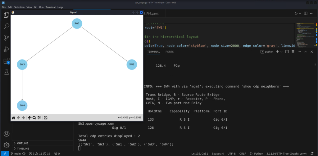
The code is below, this the part I leaned on ChatGPT to help, I am not the UI or graphical expert. The backend logic is me though. Toot me horn about the rest of the code in comments and messages on LinkedIn or social media.
def visualize_hierarchical_topology(edges):
    # Create a directed graph
    G = nx.DiGraph()

    # Add edges dynamically
    G.add_edges_from(edges)

    # Create a hierarchical layout
    def hierarchy_pos(G, root=None, width=1., vert_gap=0.2, vert_loc=0, xcenter=0.5):
        """
        Generate a hierarchical layout for the graph.
        """
        pos = _hierarchy_pos(G, root, width, vert_gap, vert_loc, xcenter)
        return pos

    def _hierarchy_pos(G, root, width=1., vert_gap=0.2, vert_loc=0, xcenter=0.5, pos=None, parent=None, parsed=[]):
        if pos is None:
            pos = {root: (xcenter, vert_loc)}
        else:
            pos[root] = (xcenter, vert_loc)
        children = list(G.neighbors(root))
        if not isinstance(G, nx.DiGraph) and parent is not None:
            children.remove(parent)
        if len(children) != 0:
            dx = width / len(children)
            nextx = xcenter - width / 2 - dx / 2
            for child in children:
                nextx += dx
                pos = _hierarchy_pos(G, child, width=dx, vert_gap=vert_gap,
                                     vert_loc=vert_loc - vert_gap, xcenter=nextx, pos=pos,
                                     parent=root, parsed=parsed)
        return pos

    # Generate hierarchical positions
    pos = hierarchy_pos(G, root="SW1")

    # Visualize the graph with the hierarchical layout
    plt.figure(figsize=(8, 6))
    nx.draw(G, pos, with_labels=True, node_color='skyblue', node_size=2000, edge_color='gray', linewidths=1, font_size=10)
    plt.title("Hierarchical Layer 2 Topology: SW1 Root")
    plt.show()
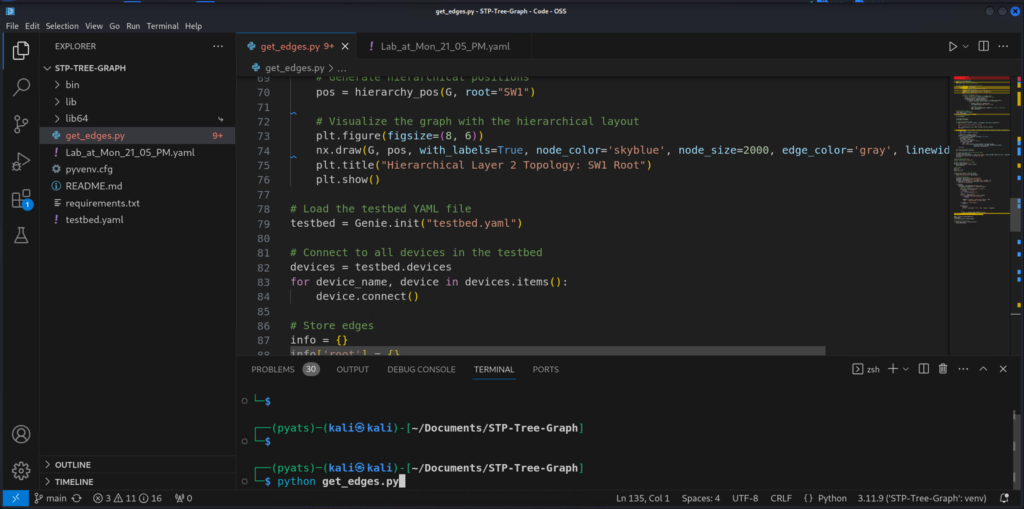
This code is then ran with the command: python get_edges.py. It is posted on GitHub https://github.com/Qwertysage/STP-Tree-Graph. This includes the repository, the YAML file (so you can recreate the topology), a virtual environment in the repo (so you can copy the environment, pip install -r requirements, and you are on the way.
Post-Lab Thoughts
Security
There are many STP features that allow for higher security: portfast, rootguard, BPDU Guard, etc. Consider this in future studies and STP related work.
The testbed.yaml file is cleartext and the passwords are generic. This is perfectly fine for a lab, but not in production.
Algorithm and Code
This is a lab, quick and dirty, not a production solution or MVP. There are ways to improve the efficiency of the script vastly, especiallly in the areas where we matched links. The algorithm is very linear and would not scale well. Brushing up on classes, sorting algorithms, and modularity, and implementing better algorithms would elevate this from lab to production.
802.1D
Spanning tree has evolved and I implore readers to learn about revisions, 802.1w and 802.1s. The fundamentals are the same. But STP now is improved. The version of spanning-tree in this lab isn’t the OG flavor. It is PVSTP+, a Cisco modified version, where you can control and prune the tree for individual or sets of VLANs and optimizing security and traffic flow even more granularly.
